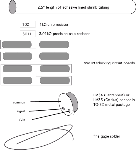

Overview) 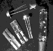 The
two circuit boards will be inter-linked in an "X" cross section for
strength and to provide grooves in which to solder the leads of the
temperature sensor at one end, and the wires from the cable at the
other end. Two chip resistors will also be soldered in the grooves.
The whole assembly will be protected and sealed inside a heat shrink
tubing with a melting liner.
The
two circuit boards will be inter-linked in an "X" cross section for
strength and to provide grooves in which to solder the leads of the
temperature sensor at one end, and the wires from the cable at the
other end. Two chip resistors will also be soldered in the grooves.
The whole assembly will be protected and sealed inside a heat shrink
tubing with a melting liner.
 Step
1) Solder the resistors onto one of the circuit boards. By hand, put
some solder on one side, and slide the resistor into the solder Let
that cool, and then solder the other end of the resistor.
Step 2) interlock the two halves of the circuit board. One half has
the two resistors, the other half has none.
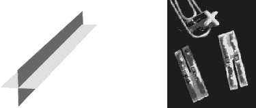
Step 3) Prepare the sensor to attache to the assembly Trim the signal and the +Vin wires to 3/16" long below the package. Trim off the small tab.
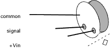
Step 4) Connect the sensor to the assembly Slider the sensor over the interlocked boards, so that the +Vin wire goes to the "102" resistor, and the signal goes to the "3011" resistor, and the long common lead goes into the groove behind the "3011" resistor. Push the sensor all the way against the top of the interlocked circuit boards. Solder all the wires to the assembly.

Step 5) Prepare the end of the three-conductor cable you are going to use. It is IMPORTANT to select the correct end of the cable. At one end, the wires will come out red-green-black (counting CCW), as called for. At the other end, they will come out red-black-green (CCW), and that would make the connection in step 6 to come difficult. Strip back the cable and leave 1/8 inch of insulation on each conductor. Leave also 3/16" of bare wire. Tin the ends of the wire to hold the strands together.
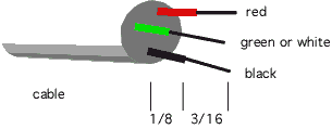
Step 6) Solder the wires to the interlocked circuit boards, at the end opposite the sensor. The red wire goes to the +Vin groove with the "102" resistor. The green or white wire goes to the signal groove with the "3011" resistor. The black wire goes to the groove with the common wire from the sensor. One groove will be empty. Fill the grooves with solder so that the grooves are filled with solder. The insulation on the wires should be nearly flush with the end of the circuit board. The black common wire from the sensor should bridge over the gap in the circuit board and be soldered in contact with the black wire.

Step 7) Prepare the opposite end of the cable. This may mean simply striping back the outer jacket of the cable, and stripping and tinning the ends of the black, green and red wires.
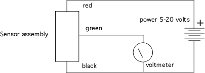
Step 8) Test the sensor. Apply a power supply voltage between 5 and 20 volts between the red (+) wire and the black (-) wire, and read the voltage between the green (signal) and black (-) wire. The signal in millivolts should be nearly equal to the air temperature in degrees F, times 10. For example, 60 degrees Fahrenheit--> 600 millivolts.
Step 9) The outer insulation on the cable can pushed up on the wires inside, so that the cable jacket comes up flush with the end of the sensor assembly.
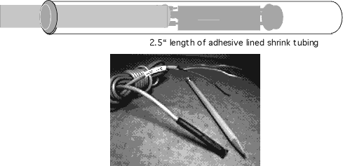
Step 10) Install the heat shrink tubing on the sensor assembly. Apply enough heat to melt the liner (110 °C). Adhesive will emerge from the tube around the cable as it shrinks. Leave 1/2" at the top above the sensor, and pinch the top closed to seal the assembly in the adhesive.
<products index>
<home> <top>
<TF & TC data sheet>
![]() < mailto:info@emesystems.com
>
< mailto:info@emesystems.com
>