Here is the syntax of the BASIC Stamp PWM command:
PWM pin,duty,cycles
This note describes the timing and details of behavior of this command. The following observations come from looking at PWM output on a 'scope, using a BASIC Stamp II. Incidentally, the manual is incorrect on some of these details, as noted below.
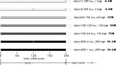
PWM works in units of cycles, each of which consists of 256 time slots. That is true for all of the BASIC Stamps. On the BS2, each cycle is 1.15 milliseconds long and each time slot is 4.5 microseconds. (The manual says approximately 1 millisecond for each cycle and 4 microseconds for the time slot) Within each cycle, a certain percentage of the time slots have the output pin at a high level, while the rest are at a low level. The duty is the percentage of time slots that are at a high level. That duty value can be from zero to slightly less than 100%, exactly 100*(0/256) up to 100*(255/256) percent. (The manual shows 255 in the denominator of the fraction, but it should really be 256--duty can not get all the way up to 100%). Here is the way the output looks for different values of duty:

The number of times that the PWM command will repeat the entire cycle it is given by the cycles parameter in the command. It can have a value of up to 255. (and a value of zero means, skip it) For example, if duty=64 and cycles=200, then the entire cycle shown above for duty=64 will be repeated 200 times, and the whole command will take 200*0.00115= 0.23 second.
The pin used by the PWM command is left in the input state upon completion of the command, so that the average level can be held on a holding capacitor. The average level is (duty/256)*5 volts.
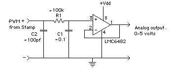
The waveforms can be filtered by a resistor and a capacitor, and buffered by an op amp if necessary to produce and analog voltage or current output from 0 to 5 volts in steps of approximately 0.4%, or 20 millivolts. The filtered value is the average of the high and the low. At the conclusion of the PWM command, the stamp leaves the pin as an input, so that the external capacitor can hold the charge.
The following is an example circuit.

The supply voltage Vdd for the op-amp can be 5 volts if the op amp is a rail to rail input and output type, such as the LMC6562. Vdd for the op-amp must be higher, say 7 o 9 volts in order to use a generic op amp like the LM358. It is best to use a CMOS input op-amp, so that the voltage on the capacitor will not "droop" from current lost into the op-amp input.
The resistor and capacitor are chosen so that the time constant of R1*C1 will effectively filter the PWM. At worst, R1*C1>>1.15E-3 seconds. For example, R1=1 megaohm, C1=0.1 microfarad makes R1*C1= 0.1 seconds, which is 100 times greater than the cycle time. But there are other considerations on the choice of R1*C1--read on.
At duty cycles near 0% and 100% the pulses are far apart and require more filtering through many cycles. On the other hand, near 50% duty cycle the pulses are close together and the filtering can be done in the course of one or two cycles. The advantage gained by using a smaller R1*C1 is a faster response.
Observe that the the high and low time is distributed evenly along the cycle of 256 time slots. For example, the 50% situation is a square wave that is high half the time and low half the time. The frequency of this square wave is 111 kilohertz, which can be filtered with a very small R1*C1 product. At 25% and at 75%, the fundamental frequency is 55.5 kilohertz, which is also easily filtered. Here are the fundamental frequencies at a few PWM duty cycles, to show how much less filtering is required if you can restrict the PWM to the middle range:
duty=1 or duty=255        870 hertz
duty=2 or duty=254       1739 hertz
duty=3 or duty=253       2609 hertz
duty=4 or duty=252       3478 hertz

duty=10 or duty=246      8696 hertz         4%

duty=64 or duty=192      55.7 kilohertz    25%
duty=128                111.3 kilohertz    50%
As a rule of thumb, the R1*C1 product should contain at least 200 pulses at the lowest expected frequency. That is 200 cycles at duty=1 or duty=255, and only one cycle at duty=128.
Cycles: The manual states that the maximum value of cycles=65535. However, it should read maximum cycles=255; if you try cycles=256, you get the same result as cycles=0.
If cycles=255, the maximum, then PWM will consist of 255 cycles of 1.115 milliseconds each. The maximum PWM episode thus takes nearly 294 milliseconds.
For driving a power MOSFET or a bipolar amplifier, one has to think about high frequency circuit design. PWM is often used to drive motors for speed control. The PWM pulses in the Stamp version of PWM are 4.5 microseconds long, so the amplifier slew rates and transistor Ft parameters have to be fast, well less than one microsecond. One also has to consider the possibility of rf radiation, due to high frequency transitions. It is difficult to transmit this form of PWM over a long cable. There is another form of PWM that maintains a constant frequency and varies the overall duty cycle.
The microcode algorithm for creating the BASIC Stamp kind of PWM is very simple. Simply add the "duty" to an accumulator. The pin is set equal to the carry from the addition. Here is how it works--roll your own "slow" PWM:
' {$STAMP BS2}
' {$PBASIC 2.5}
' program to mimic Stamp PWM output
' but slow, on P0
' to demonstrate how PWM is created
' this is also useful where slow PWM is needed.
duty    CON    4    ' choose duty from 0 to 255
X       VAR    NIB     ' accumulator for the state machine
oldx    VAR    NIB
LOW 4
DO
  X = X + duty      ' add duty to accumulator
  IF x < oldx THEN OUT4=1 ELSE OUT4=0     ' move carry to output pin
  'OUT4 = x MIN oldx - oldx MAX 1   ' another way to do it, computed
  oldx = x
LOOP
The above uses a 4 bit accumulator for illustration. When
duty=8, there is a carry for every other slot, so the
output changes state every time: high-low-high-low, for a
proportionally duty cycle of 50%. If the duty=4, then you can verify
that it is low-low-low-high in a repeating pattern for an
proportional duty cycle of 25%. And duty=12 gives low-high-high-high
repeating for 75%. And so on. (Left as an exercise!). This stamp
routine is much slower than the actual PWM command.