This document contains information about IrDA and how to
obtain it on the Stamp using the MAX3100 UART. It also contains information
about the MAX3100 family of UARTs, which are very useful both for IrDA and for
conventional RS232.
Contents:
IRDA
Stamp IrDA interface using the MAX3100, with code
MAX3100 configuration word
Palm pda and IrDAlinks:
- <http://www.irda.org/>
- IrDA standards committee.
- <http://www.maxim-ic.com>
- data for the MAXIM chips, MAX3100, MAX3110 and others in the family of SPI interface UARTs
- <http://www.wd5gnr.com/suart.htm>
- Al Williams' description and code for the MAX3110, bit-banged SPI
- <http://devices.sapp.org/micro/stamp2sx/max3110/>
- a MIDI interface using the MAX3110
Infrared communication via IrDA is built into many portable computers and PDAs, such as the Palm, Windows CE machines, the old HP200LX, and many laptops. It provides a convenient way to download data loggers and to communicate with other mobile platforms without wires over short distances.
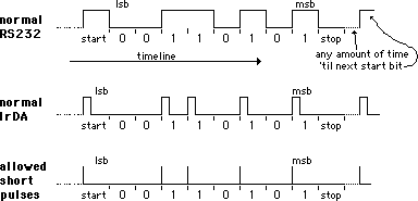
The IrDA protocol is very similar to standard RS232, as illustrated by the following diagram.

Normal RS232 uses voltage levels to transmit the data. From left to right on the timeline, the voltage is in a resting low state when high start bit comes along, followed by 8 data bits, and last at least one low stop bit. A new character can start at any time after the conclusion of the previous stop bit(s). There are several conventions. RS232 is an "inverted" logic, so that a logical "1", or "mark" is represented by a low level. This comes from old teletype days when a pen was down to make a "mark" and lifted up by an electrical current in a magnet to make a "space" or zero. Also, by convention, the data is transmitted least significant bit first, and a logical 1 is transmitted as a low level and a logical zero is transmitted as a high level. At 2400 baud, the length of each bit period is 1/2400=417 microseconds.
You can easily imagine how to transmit the same data by light waves. You could leave the light ON to represent the "mark" state, in which case "space" would be light OFF. But if characters are sent only infrequently, that could waste a lot of power, because the light would be ON most of the time. Remember, we are usually talking about portable battery powered equipment. Or vice versa, light OFF could represent "mark" and light ON the "space". But still that would consume more power than necessary. The designers of the IrDA protocol realized this and decided to make flash of the light represent the logical "0" and to make the flash brief, shorter than the standard RS232 bit period. This allows the flash to be very bright, and to transmit further for a given input of battery power. The accepted length of a flash of light to represent a "0" is 3/16 of the bit period. The flash of light for IrDA at 2400 baud would be 78 microseconds instead of 417 microseconds, but the bit period is still 417 microseconds. The 3/16 rule holds for any baud rate, not just 2400.
There is another catch. The IrDA specification for low speed (115 kbaud and under!) communications allows the length of the transmitted pulse to be much shorter than 3/16 of the bit period. The pulse of light for any baud rate can be low as 1.7 microseconds in duration to represent a "0". (1.7 microseconds is 3/16 of the bit period at 115kbaud.) This very short pulse allows a transmitter to create a very bright flash, and still achieve low battery consumption.
In paractice IrDA transmitters and receivers vary somewhat in the pulse width that they transmit and what they will receive correctly. This is something to check if you are having trouble getting one IrDA device to talk to another.
The light is usually emitted at 880 nm. Infrared receivers usually has a fairly wide bandwidth to accept energy from any IR led, 880 &endash; 940 nm.
The IrDA transmitter circuitry must be able to turn normal RS232 into the short pulses of IrDA. This takes a clock sychronized with the baud rate. It is not possible to turn normal RS232 into IrDA pulses simply by keying on the transitions in the signal. There are not necessarily transistions in the data, for example, the ascii null character is all zeros, so the start bit plus the 8 zero bits forms one long pulse 9 bits long with no transitions:
___---------_____     ' transmission of ascii null
   S00000000s         ' start and data bits are "0"s
___|||||||||_____     ' IrDA version, 9 short light pulses

___-_____________     ' transmission of ascii $ff
   S11111111s         ' data and stop bits are "1"s
___|_____________     ' IrDA version, one short light pulse
The IrDA receive circuitry must be able to detect the short pulses of light and "stretch" them to fill the standard bit width at the current baud rate for input to standard RS232 serial ports.
The above describes what is called the "physical layer" of IrDA. There are other "layers" that implement protocols for such things as sending packets of error free data and for automatic negotiation of baud rate. I will not get into that here. The Stamp's limited brain would have trouble implementing those protocols. We are just dealing here with the physical layer, where IrDA is simply a wireless RS232 substitute. The link must be tight to avoid errors, or you must implement some ad-hoc error checking in software at both ends.
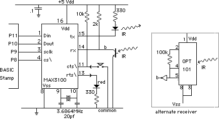
The Stamp itself has an RS232 port, but it does not have the capability to generate and receive the short pulses of either normal or short IrDA. For that we turn to the MAX3100. It is a UART (Universal Asynchronous Receiver Transmitter) that communicates with the BASIC Stamp over the SPI interface, and sends and receives the data to and from the outside world in the form of RS232. One of its options is to send and receive the data directly as IrDA. All it takes is an IR emitting diode and an IR photodetector. The MAX3100 requires a 3.6864 mhz crystal on which it bases its baud rates.

The main circuit shows a simple phototransistor as the receiver
connected to the rx pin, which is fine for low speeds and short
distances. For output from the tx pin, a high-efficiency IR led is
driven directly, sinking current to turn the light on. This is a very
short range circuit, a one inch range. The alternate
receiver uses a Burr-Brown integerated photodiode amplifier to
acheive greater sensitivity and speed. The output "b" from the OPT101
+ inverter circuit would replace the phototransistor input to the rx
pin on the MAX3100. If more power is needed on the transmit side, it
can be driven by a power transistor or a more capable current
source.
A third and probably the best alternative for the longest distance of operation is one of the dedicated IrDA modules, that have an IR LED with a driver circuit and also a PIN photodiode with a high gain high speed amplifier all integrated onto one chip. For example, the Aligent (Hewlett Packard) HSDL series. (E.G. HSDL3209 or HSDL3220)
The red led and the pushbutton shown in the circuit connected to the rts\ output and cts\ input signal lines on the MAX3100. These connections are only for test purposes as illustrated in the program below.
The MAX3100 has additional desirable features. One of these is a buffer that can hold up to 8 received characters until the Stamp gets around to reading them out. Another feature is a sleep mode, with automatic wakeup upon detection of a start bit. (Note that the MAX3100 operates in "non-inverted" mode, with a logical "1" or "mark" state being a high level. For normal RS232, MAX3100 would interface with the RS232 line through an inverting RS232 driver chip.)
Here is a simple getting-started demo of some of the main commands required to use the MAX3100. The demo first configures the MAX3100 for 2400 baud using the IrDA timing at the tx and rx pins. It then transmits "the quick brown fox jumps over the lazy dog" plus a CRLF. Then it goes into a loop to receive data from the IrDA port and print it on the debug screen. If the pushbutton on the above circuit is pressed, the program goes back and transmits the "fox and lazy dog" phrase again, so long as the pushbutton is down. The rts line is made high to turn on the red led when the MAX3100 is transmitting.
' {$stamp bs2e}
' program for the MAX3100 in IR mode
' with 3.6864mhz crystal
' (c) 2001  Tracy Allen, EME Systems
outs=$0100
dirs=$ffff
din	con	11	' data sent from stamp to uart
dout	con	10	' data out from uart to stamp
sclk	con	9	' data clock
cs	con	8	' active low chip select
fox	data	"the quick brown fox jumps over the lazy dog",13,10,0
char	var	word    ' will combine 8-bit command/status and 8-bit data
ix	var	byte
rts	var	char.byte1.bit1	' for data send
cts	var	char.byte1.bit1	' for data read
tst	var	bit
Rbit	var	char.byte1.bit7

high cs
pause 100

' ------------------------------
' set the mode to 2400 baud, IrDA
' this writes to the configuration register
writemode:
low cs
  shiftout din,sclk,msbfirst,[$C08D\16]
high cs

' ------------------------------
' transmits the message in data space "fox"
' "the quick brown fox...  +CRLF
sendfox:
  char.byte1=$80   ' make rts high, red led on
                   ' rts is bit 1, pin is made high when bit is low.
  ix=0
sendfox1:        ' this loop gets fox, null terminated string.
  read ix,char.byte0
  if char.byte0=0 then sendfoxend
sendfox2:
  low cs
  pulsout sclk,2    ' get one bit
  tst=dout          ' test that transmit buffer is empty
  high cs
  if tst=1 then sendfox2  ' loop back until ready
  low cs            ' now send the character
  shiftout din,sclk,msbfirst,[char\16]
  high cs
  ix=ix+1
  goto sendfox1      ' look for next char to send
sendfoxend:
  low cs            ' now turn off RTS pin
                     ' the TE\ bit=1, so no data is transmitted.
  shiftout din,sclk,msbfirst,[$8600\16]
  high cs
  goto terminal      ' back to receiving characters
                     ' and testing cts

' ------------------------------
' now enter a loop to receive data and print it on a debug screen
' jumps to sendfox routine when the hardware cts line is low
' by pressing the pushbutton in the above circuit
terminal:
low din    ' sequence to receive data, both 8-bit status and 8-bit data
  low cs
    shiftin dout,sclk,msbpre,[char\16]  ' 16 bits total
  high cs
  if cts then sendfox    ' Jump to sendfox is pushbutton down.
                          ' cts bit is high when the pin is low
  if Rbit=0 then terminal  ' skip printing if there is no character
                           ' Rbit is the flag for this.
  debug char.byte0     ' print the character
 goto terminal  ' receive more bytes
To use this with an HP200LX, enter the HP COMM program and choose the connect menu. Choose the infrared port and 2400 baud. Now with the two infrared ports coupled, you should see the fox message printed on the HP screen, and what you type on the HP200LX keyboard should be echoed on the Stamp debug screen.
Note: The MAX3100 is one of those IrDA devices that generates an output light flash that is precisely 3/16 of the bit width. And it expects the same for its input. It will reject incoming flashes if they are less than 1/8 of the bit width. That is a problem with some devices that generate a shorter pulse. A pulse stretcher can be added to the circuit for use at a fixed baud rate.
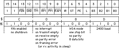
Here is a diagram that shows how the configuration word used above, $C08D, is determined. There are quite a few options, but it is all quite straightforward if you study the MAX3100 data sheet. The baud rate assumes a 3.6864mhz crystal.

If you want to use the MAX3100 as a standard UART, you would connect the rx and tx lines (pins 12 and 13 on the MAX3100) not to LEDs, but through a line driver like the MAX232 or optoisolators to a hardwired RS232 cable. For example, a configuration word of $D14B would set wired connection (instead of IrDA), 9600 baud, 2 stop bits (instead of 1), enable the 8-byte FIFO, and instruct the MAX3100 to shut down its baud rate oscillator (10µamps current, but SPI interface still active), and generate a low level on the IRQ\ pin when there is activity on the RX serial line. The IRQ\ line is not used in the above circuit. See the MAX3100 data sheet for all the details.
One great program for looking using the serial and IrDA capabilities
of the Palm is the program, "Online" available from Conklin
Systems:
Online is a terminal emulator.
The Palm PDA is one of
those devices mentioned above that transmits very short pulses in
order to conserve power, instead of the generic 3/16 bit width. One fix
to the above circuit to make it work at 2400 baud would a pulse
stretcher, added to the
received data line. Each pulse emanating from the Palm needs to be
stretched by our circuit to at least 1/8
of the bit period for the MAX3100 to recognize it. Alternatively,
operate the Palm and the MAX3100 at 115.2 kbaud or perhaps 57.6 kbaud.
As explained above, the light pulses from the Palm will then be
long enough to satisfy the MAX3100.
At 115.2 kbaud, the pulses of light are 1.7 microseconds long.
However, the simple circuits above using the phototransistor or
the OPT101 do not have sufficient bandwidth to deal with microsecond
pulses. The OPT101 has a 15 khz bandwidth, but for 115.2kbaud
operation, the receiver circuit for would require a bandwidth of 1
megahertz or better. For this purpose, the HSDL3000 series IrDA
transceiver would be the best bet.
Here are some messages from the NSBASIC user group concerning access to the IrDA port on the Palm (Note, this information is quite old no (2005) and the user should look for more recent information. The Palm has evolved considerably through the years :
More later...